Making a Friction Test Ring

Secrets, tips, tools, design considerations, materials, the "science" behind it all, and other topics related to building the cars and semi-trucks.
Post Reply
Jeff Piazza
Pine Head
Pine Head
Posts: 83
Joined: Thu Apr 10, 2008 12:49 pm
Location: Wellesley, Massachusetts

Making a Friction Test Ring

Post by Jeff Piazza »

A recent derbytalk.com thread (viewtopic.php?t=4420) inspired me to try building Stan Pope's spin testing rig described at http://www.stanpope.net/pwafm.htm. I found building the rig to be a project in itself, and wanted to share the details of the experience here.

The goal is a roughly two-inch diameter wooden ring that will surround a pinewood derby wheel. The ring needs to provide about 2 ounces of weight, to simulate the load on a wheel during the race.

For my first attempt, I tried using a simple hole -- a 2" diameter for the outside, and a 1 1/4" diameter for the inside. It turns out my hole saw, and I assume others commonly available, have a lot of runout, and are unsuitable for attempting to do work at any real precision. (They make a perfectly fine hole for a door knob, and that's their main function, I think.) I was unhappy with the ring that resulted, as it had on outside diameter of about 1 7/8" or less, and an inside diameter that I felt was too large.

I also discovered that a ring of these dimensions that's made of wood is way too light -- about 0.3 ounces, rather than the desired 2 ounces. So I needed to find some way to add some significant weight to the ring.

I ended up using my router and a home-made router "table" to fashion the ring.

The router "table" is really just a piece of 1/2" MDF that attaches to the router base. There are also two adjustable fences, also of 1/2" MDF. (This set-up is mainly for routing out weight pockets in the bottom of derby cars.)

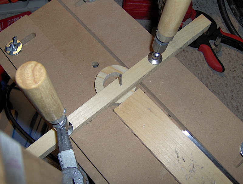
I put a nail through a piece of 3/4" x 3/4" scrap, and then drove the point of the nail into the middle of a piece of stock for the ring. The scrap is then clamped across the top of the two fences, and acts as an overhead arm that lets me locate the pivot at any desired distance from the router bit. (I was concerned that this basic nail-as-pivot arrangement would develop some play during use, but this turned out not to be the case.)

Image

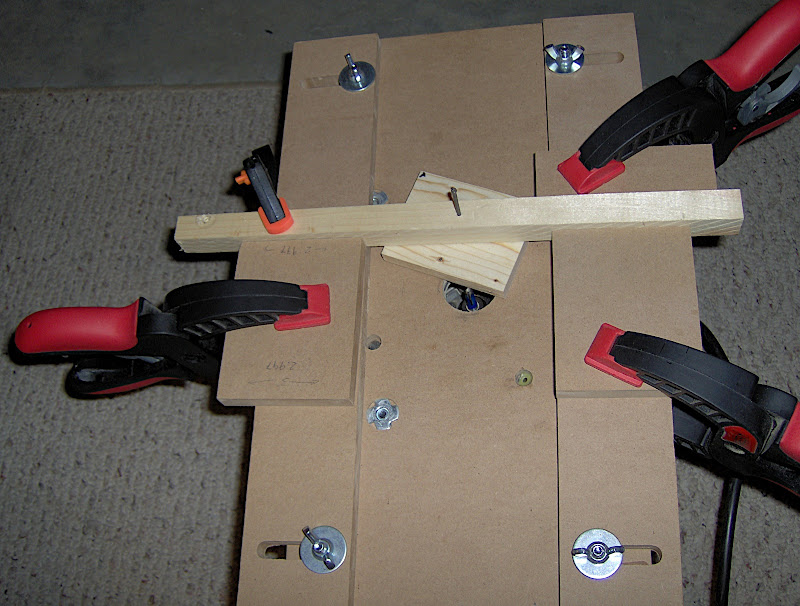
One thing I didn't pay enough attention to initially was managing the arm's travel in the Y dimension (left to right movement in the picture above). It's obvious with a little thought that the pivot-to-bit distance depends on both the X- and Y-location of the pivot, so it's important to mark where the arm crosses each fence. It's also important that the fences be parallel to each other, or the marks won't really mean anything when you change the X-location. After the picture above was taken, I added some F-clamps to the arm itself, to hold it absolutely steady.

In hindsight, setting the bit-to-pivot distance would have been made easier if I'd first centered the pivot on the router bit, without the stock in place, and marked that zero point on both fences. The pivot-to-bit distance could then be established by clamping the arm at a measured distance along both fences. Having not done this, I had a set each distance by trial and error.

I first cut the outside diameter with a 1/4" bit, raising the bit 1/8" with each pass. On the fourth pass the bit cuts all the way through the 1/2" stock, and you have a disc where previously you had a rectangle.

I then switched to a 1/8" bit, also raising 1/8" on each pass, but this time only cutting a 3/8" deep channel in the ring. I was quite pleased with how this came out, really much better than I would have thought possible (at least for me).

Image

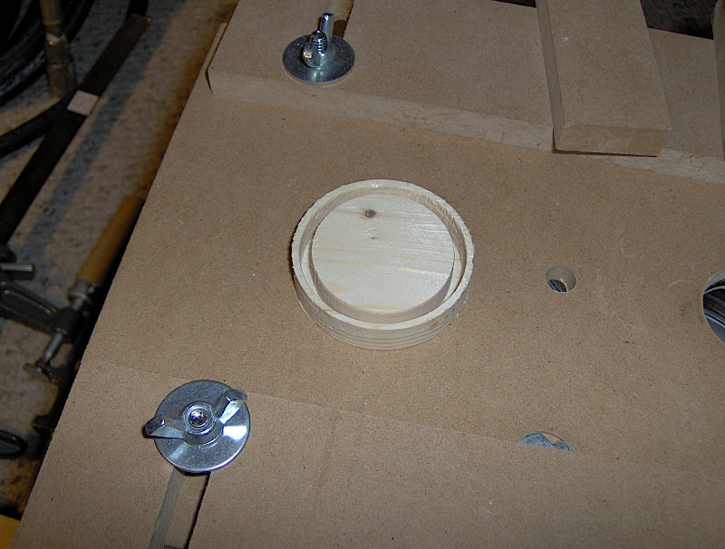
Finally, I switched back to the 1/4" bit and cut through the disc again to form the inside diameter of the ring. Setting the radius for this cut involved a lot of trial and error, since it's desired to fit
the plastic car wheel pretty closely. (As the very last bit of material is removed, the ring becomes disconnected from the pivot, resulting in a small defect in the inner wall. I was later able to
correct this with a rotary tool sanding drum.)

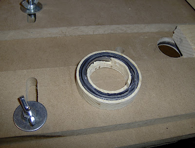
I then cut a strip of lead flashing 3/8" by 12", and inlaid it into the routed-out channel in the ring by wrapping around twice. (I find that my cheap Harbor Freight paper cutter works great for making strips of lead flashing.) The ring now weighed about 1.4 ounces; 1.5 when the derby wheel is added.

Image

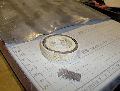
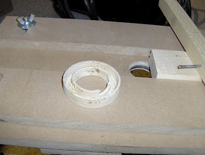
To make up the last half ounce or so, I considered applying a ring of lead flashing, seen here. This would have worked (total of about 2.2 ounces), but the lead ring looked terrible. (I'm reluctant to use things like a rotary tool because of the lead dust and chips that would be generated. Unfortunately, tin snips and the like leave a pretty rough edge when trying to cut circular lines.)

Image

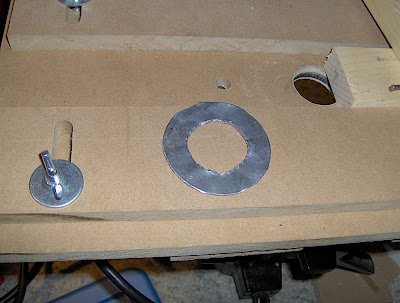
Instead, I decided to try widening the channel in the ring, and adding another strip of lead. With the original pivot no longer available, I added a third fence to my router set up, and used the arm-and-nail pivot as a point fence in the middle of the ring. (I also moved the side fences in so they just touched the outside of the ring.)

Image

With these fences all in place, I was able to use the 1/8" bit again to
widen the channel. Unfortunately, there was some tear-out in the ring's inner wall, probably because there ended up being just a little more play in the set-up than there should have been.

Image

However, most of the wall is OK, and I was able to add the third strip of lead. The ring now weighs 1.8 ounces or so.

Image

Here's the jig with a wheel in place, using three pieces of rubber band as shims. Note that, with only three points of contact on the inner wall, the damaged sections have only cosmetic effect.

Image

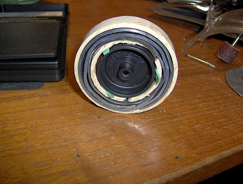
After painting, I hope to pursue Stan's suggestion of adding a revolution counter of some kind, probably by cannibalizing the wheel encoder from an old non-optical mouse.
Last edited by Jeff Piazza on Sat Apr 03, 2010 6:42 am, edited 1 time in total.
User avatar
PWD_addict
Master Pine Head
Master Pine Head
Posts: 705
Joined: Mon Jan 22, 2007 10:35 am
Location: Middle River, Maryland

Re: Making a Friction Test Ring

Post by PWD_addict »

Jeff--
That's fantastic!!! I didn't see Stan's plans previously so I had no idea how (relatively) easy it would be. THe problem I was having (in my engineer's mind) was how to get the wheel to fit in the hole. The rubber band shims were not in my thinking box. Brilliant to both you and Stan.
10range
Pine Head
Pine Head
Posts: 73
Joined: Fri Dec 19, 2008 6:41 am
Location: South Bend, indiana

Re: Making a Friction Test Ring

Post by 10range »

One word of caution I would give you is to make sure that the rig is balanced. If it is out of balance, it could easily effect spin times. On my test rig and the one that I built my to model off of, the ring was pressed directly on to the wheel. On the one that I built, I used wheels that I was not planning on using again because it left some marks on the wheels when pressed on.

If you can work out a way to electronically count the rotations I am curious to hear your results. I would also be curious to see if you would be able to measure something like the amount of time it takes for each wheel to get to 50 or 100 revolutions. I think that this would be a more accurate test than total spin time. I feel this would be a more accurate test because on the track, the wheel will never come to a stop. I am guessing that liquids and graphites will behave different when running at speeds slower than the would be on track. This would also be a much more difficult test to set up than the total spin times.
User avatar
PWD_addict
Master Pine Head
Master Pine Head
Posts: 705
Joined: Mon Jan 22, 2007 10:35 am
Location: Middle River, Maryland

Re: Making a Friction Test Ring

Post by PWD_addict »

10range wrote:One word of caution I would give you is to make sure that the rig is balanced. If it is out of balance, it could easily effect spin times. On my test rig and the one that I built my to model off of, the ring was pressed directly on to the wheel. On the one that I built, I used wheels that I was not planning on using again because it left some marks on the wheels when pressed on.
You could melt some lead and pour it in the channel in the ring to give you better balance. I've got lots of friends that melt lead for fishing weights.
Jeff Piazza
Pine Head
Pine Head
Posts: 83
Joined: Thu Apr 10, 2008 12:49 pm
Location: Wellesley, Massachusetts

Re: Making a Friction Test Ring

Post by Jeff Piazza »

Yes, balance is definitely a concern -- there's a clear heavy point at present. Lead flashing seems not to be of uniform thickness, although I can't tell how much that's due to handling after it leaves the store.

I may look at melting lead if there's a "v2.0". I'm pretty ambivalent about the whole melting thing -- it's pretty cool, but pretty dangerous.

I'm hoping to use the ring as the basis for my Webelos' Science belt loop project.

One detail I forgot to mention - the outside diameter of the ring ended up at about 2 1/8". This was originally unintentional, but with the final width of the weight channel, I don't think a 2" ring would have worked.
User avatar
Stan Pope
Pine Head Legend
Pine Head Legend
Posts: 6856
Joined: Sat Jul 05, 2003 7:01 pm
Location: Morton, Illinois
Contact:

Re: Making a Friction Test Ring

Post by Stan Pope »

Nice work!

Pouring can be tricky, too. Gotta keep the channel level. The lead will harden almost immediately rather than do the "liquid self leveling" thing that water would do.

The 2 inch, 2 ounce target is just that. 2 ounces approximates the load on the rear wheels of a 4:1 distributed PWD car. 2" approximates the net effect of g-force on the slope. The analogue is not exact, but is close.

Adding the rotation counter and timing a specific number of rotations is better still, since that includes "start-up" frictions into the measure!
Stan
"If it's not for the boys, it's for the birds!"
User avatar
PWD
Master Pine Head
Master Pine Head
Posts: 724
Joined: Thu Dec 04, 2003 7:24 am

Re: Making a Friction Test Ring

Post by PWD »

What we have used is several big washers that I then glued together with super glue to make them thicker. I then coated the inside of the washers with foam that I purchased at Michaels. It has a sticky back. The wheel then fit in perfectly. I was also then able to get the weight of equal to 1/3 of 5ozs. The weight was also then balanced.
Jeff Piazza
Pine Head
Pine Head
Posts: 83
Joined: Thu Apr 10, 2008 12:49 pm
Location: Wellesley, Massachusetts

Re: Making a Friction Test Ring

Post by Jeff Piazza »

I've had only limited time to pursue this further during the week, but it looks like the balancing issues are greater than I thought. The whole assembly shows fairly extreme "chatter" beyond a relatively low speed.

I tried doing a static balance by identifying the heavy side and attempting to estimate the weight difference by weighing opposite points on the ring. (This is similar to the two-scale method of figuring COM for a car. I only have the one scale, but I used a matching-height support for the unweighed edge.) The difference between the heavy side and the opposite side was only about .6 grams, and the total matched the ring total weight. By adding some small pieces of lead I was able to achieve static balance, in the sense that the wheel remains still at most orientations. (There's one orientation from which the wheel still wants to go 1/8 turn.)

Dynamic balance seems to be a whole different level of game! As I said, above a certain speed, the whole assembly suddenly develops a chattering motion, no longer spinning solely about the axle. I don't have any idea where to begin to identify what the issue here is.

(As an aside, I did observe that a smooth axle makes a big difference in reducing, but not eliminating, the tendency to chatter.)

For the all the fun it was to overcome the challenges of making a wood ring, I'm thinking maybe this is a dead end.

PWD - Where do you buy your "big" washers? I located at least one source for 1.25" ID flat washers (don't know the OD), but they're certainly not available at the local Home Depot. Any other details you can share?

/JEP
User avatar
ohiofitter
Master Pine Head
Master Pine Head
Posts: 693
Joined: Sat Feb 03, 2007 10:30 am
Location: Uniontown,Ohio

Re: Making a Friction Test Ring

Post by ohiofitter »

Jeff that is great you made the friction ring.But I made a car with fenders and used a 1 1/4 hole saw and did not car for it I felt the wheel wells were to big so I drop down to a 1 3/8 hole saw and they came out better...If you ever make another or try to improve on yours give that a try
User avatar
PWD
Master Pine Head
Master Pine Head
Posts: 724
Joined: Thu Dec 04, 2003 7:24 am

Re: Making a Friction Test Ring

Post by PWD »

No you can't get them at Home Depot, Lowes or Ace. I don't remember the place but they were online and then had an outlet locally so I could pick them up. I think it was MSC Industrial Supplies. A URL is below:

http://www1.mscdirect.com/CGI/N2SRHI?PM ... L391316886

The weight was pretty easy to get right. Just need to find the right ID and then figure how how many washers you need to get the correct thickness and then vary the OD accordingly.

I will try to measure when I get home.

The device that Stan outlined a couple of years ago is really cool and a great device for educating kids. Also a great conversation piece when cubs come over to build cars. I also made the wind tunnel that Randy from MaxV outlined a few years ago. Also a great conversation piece and very educational.

I have also built a number of other tools to make it easy for the cubs to build their own cars while educating them.
User avatar
SlartyBartFast
Master Pine Head
Master Pine Head
Posts: 272
Joined: Mon Feb 12, 2007 11:30 am
Location: Montreal, Quebec

Re: Making a Friction Test Ring

Post by SlartyBartFast »

So when is someone going to build a PWD rolling road test rig?

Just like a real car dyno but with the dyno spinning the wheels instead of the other way round.

Could test a car for stability, friction, drift/railriding, max speed...
User avatar
ohiofitter
Master Pine Head
Master Pine Head
Posts: 693
Joined: Sat Feb 03, 2007 10:30 am
Location: Uniontown,Ohio

Re: Making a Friction Test Ring

Post by ohiofitter »

PWD........................Just for grins and giggles I was looking into making a wind tunnel as well...but when it comes to it how do you read the numbers...lets say your car in a tunnel lifted the weight so it had just 1 ounce on it is this good or bad.......I have a friend that's a sheet metal worker and we were going to make ours out of a 20 box fan he's going to make a reducer down to a 8 by 12 duck...he has 90 degree corners that have a type of filter in them...........back to another strait piece of duct work with a door then into another reducer to make a true tunnel......
User avatar
PWD
Master Pine Head
Master Pine Head
Posts: 724
Joined: Thu Dec 04, 2003 7:24 am

Re: Making a Friction Test Ring

Post by PWD »

The idea is more to compare the wind resistance of one design versus another.

I was curious if building a car with a hole in the middle, to reduce weight, would make a difference from a wind resistance. Plus we often build cars with two holes. Did not see really any significant difference in the wind tunnel.

I really don't ever use it. It is more of a conversation piece and to explain things to my boys.
User avatar
SlartyBartFast
Master Pine Head
Master Pine Head
Posts: 272
Joined: Mon Feb 12, 2007 11:30 am
Location: Montreal, Quebec

Re: Making a Friction Test Ring

Post by SlartyBartFast »

ohiofitter wrote:PWD........................Just for grins and giggles I was looking into making a wind tunnel as well...but when it comes to it how do you read the numbers...lets say your car in a tunnel lifted the weight so it had just 1 ounce on it is this good or bad.......I have a friend that's a sheet metal worker and we were going to make ours out of a 20 box fan he's going to make a reducer down to a 8 by 12 duck...he has 90 degree corners that have a type of filter in them...........back to another strait piece of duct work with a door then into another reducer to make a true tunnel......
Any aerodynamically reduced lift or downforce is bad. Both are the result of drag which will slow you down.
Post Reply