
This item is not on the original post. Where should it be in the circuit? I want to make sure I am protecting the right thing(s). Thanks!*5 J's* wrote: Circuit protector $0.34
Solenoid Start Gate Circuit
Re: Start Gate
Re: Start Gate
That is the part I was considering. Thanks.habcdb wrote:http://www.derbytalk.com/viewtopic.php?f=5&t=2448
http://web.archive.org/web/200710291453 ... matic.html" target="_blank
Radio shack part number 276-2072. This is the one I used, but do not mount it to an aluminum box without isolating it from the box. It will trigger the switch or ground out. Not sure which, but it would activate the solenoid when the metal base of the switch touched the box. The box was grounded.

Re: Start Gate
TimInOhio wrote:That is the part I was considering. Thanks.habcdb wrote:http://www.derbytalk.com/viewtopic.php?f=5&t=2448
http://web.archive.org/web/200710291453 ... matic.html" target="_blank
Radio shack part number 276-2072. This is the one I used, but do not mount it to an aluminum box without isolating it from the box. It will trigger the switch or ground out. Not sure which, but it would activate the solenoid when the metal base of the switch touched the box. The box was grounded.
Welcome, I just finished building one. I used this box from radio shack. Catalog #: 270-238
It worked great. I mounted all the parts to the bottom and mounted the top to the track. I would also recommend installing a bearing on the start gate lever where it makes contact with the gate. I found this recommendation on another web site.
CDB Racing
Re: Start Gate
Thanks again.habcdb wrote:TimInOhio wrote:
That is the part I was considering. Thanks.
Welcome, I just finished building one. I used this box from radio shack. Catalog #: 270-238
It worked great. I mounted all the parts to the bottom and mounted the top to the track. I would also recommend installing a bearing on the start gate lever where it makes contact with the gate. I found this recommendation on another web site.
Do you mean install a bearing so that the lip of the gate rides on a bearing instead of contacting the start lever directly? Do you have a pic, or can you point me to the other board (via PM is fine)? I've heard/seen of that before - but can't recall the specifics.
Re: Start Gate
Anyone? Do I just put it inline with the 12VDC?TimInOhio wrote:This item is not on the original post. Where should it be in the circuit? I want to make sure I am protecting the right thing(s). Thanks!*5 J's* wrote: Circuit protector $0.34
Thanks!!!
Re: Start Gate
sorry - missed the original post - yes inline or in "series" with the 12vTimInOhio wrote:Anyone? Do I just put it inline with the 12VDC?TimInOhio wrote: This item is not on the original post. Where should it be in the circuit? I want to make sure I am protecting the right thing(s). Thanks!
Thanks!!!
Re: Start Gate
Thanks for the clarification, 5 J's. I have the parts ordered and should be able to get one of these built for me and another for the Pack by this weekend!*5 J's* wrote:sorry - missed the original post - yes inline or in "series" with the 12vTimInOhio wrote:
Anyone? Do I just put it inline with the 12VDC?
Thanks!!!
Thanks again.
Tim
Re: Start Gate
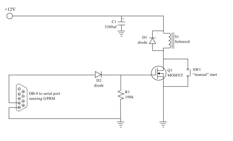
So I use only the +12VDC from the power supply, and connect all the grounds to pin 5 on the serial port?*5 J's* wrote:Below is a circuit for a start gate operated by GPRM via the serial port.
12Vdc will be supplied via a 12Vdc AC adapter (500mA or greater). Most people probably have one kicking around or you could order one such as this 12Vdc AC adapter. Note which size plug it is using. This one is using a 2.5mm, so I would need a 2.5mm female jack such as this 2.5MM DC JACK, PANEL MOUNT.
C1 is a 3300uF capacitor and is used as low-pass filter to clean the 12Vdc power.
S1 is the solenoid. I have two options. This one has a 1/4" pull or this door lock actuator which has a 3/4" pull. NOTE: Solenoid did not have enough power - ordered this one instead
D1 is a diode and is reversed biased in the circuit. It is used to shunt the current developed as the field of the solenoid collapses.
Q1 is an N-channel MOSFET and is used as the switch.
R1 is a 100k resistor and is used to prevent noise for triggering the MOSFET.
D2 is another diode and is used to prevent current flow towards the serial port on the computer.
I have also incorporated a normally open momentary switch (SW1) that can be used to "manually" operate the solenoid.
Operation is as follows: The +12v will be applied to the circuit but will sit on the drain of the Q1 MOSFET. GPRM will send the open start gate command to the gate on the MOSFET via pin 4 of the DB-9 connector. One this voltage is applied to the gate of Q1, Q1 will allow current flow from the drain to the source. This will activate the solenoid, allowing the start gate to open. Once GPRM stops sending voltage to the gate of Q1, Q1 will stop conducting and the solenoid will return and it's collapsing field will be shunted via the D1 diode.
This can easily be modified to have a light tree trigger the solenoid vice GPRM.
My plan is to integrate the wires from pin 4 and pin 5 of the DB-9 into the wires running between the RJ-11 jack's used for the gate switch on the Microwizard timer, such that I only have one 4 conductor wire running between the start gate and the timer. Then one serial cable from the timer to the computer.
What do you all think? Is there anything I am missing or other things I should integrate? This should me a relatively inexpensive mod for my track. Should be about $10 in parts plus shipping costs.
I am not sure what "device" the solenoid will pull on to open the gate. I like the lever Sporty is using but I'm not sure where I can pick one up. I could easily make something I suppose.
Re: Start Gate
Well the ground for the 12V needs to be common to that point as well. How you actually hook the wire is up to you. I don't have my start gate in front of me, but I think I ran wire from the ground side of the 2.5MM DC JACK, PANEL MOUNT to the capacitor, then a wire from this same point to the gnd on the MOSFET,where I also had one side of the resistor tied in, then ran a wire from this pint to Pin 5 on the DB9.
It all depends on how you have it mounted, but all these points (ground on the power pack, cap, mosfet, resistor, and pin 5 of the DB9) need to be common, or electrically tied together.
It all depends on how you have it mounted, but all these points (ground on the power pack, cap, mosfet, resistor, and pin 5 of the DB9) need to be common, or electrically tied together.
Re: Start Gate
The -12VDC is same as the ground?*5 J's* wrote:Well the ground for the 12V needs to be common to that point as well. How you actually hook the wire is up to you. I don't have my start gate in front of me, but I think I ran wire from the ground side of the 2.5MM DC JACK, PANEL MOUNT to the capacitor, then a wire from this same point to the gnd on the MOSFET,where I also had one side of the resistor tied in, then ran a wire from this pint to Pin 5 on the DB9.
It all depends on how you have it mounted, but all these points (ground on the power pack, cap, mosfet, resistor, and pin 5 of the DB9) need to be common, or electrically tied together.
Re: Start Gate
I'm not sure what you have for a power supply or how it's labeled - but picture your car battery at your power supply - one side is +12V the other is ground or 0VDC.TimInOhio wrote:The -12VDC is same as the ground?
There are power supplies such as those used in computers that have multiple output voltages at it is possible to have an actual -12VDC. That is not what you want. If you hooked between a +12VDC and -12VDC you would have a 24VDC potential.
If you are using a standard 12VDC wall pack the center should be +12VDC and the outer should be ground. Same as your 12V "cigarette lighter" in your vehicle - center is hot (+12V), outside is ground (0V).
Re: Start Gate
I have a wall wart labeled output: 12VDC 500mA, with negative polarity on the tip and positive polarity on the outer shield.*5 J's* wrote:I'm not sure what you have for a power supply or how it's labeled - but picture your car battery at your power supply - one side is +12V the other is ground or 0VDC.TimInOhio wrote:The -12VDC is same as the ground?
There are power supplies such as those used in computers that have multiple output voltages at it is possible to have an actual -12VDC. That is not what you want. If you hooked between a +12VDC and -12VDC you would have a 24VDC potential.
If you are using a standard 12VDC wall pack the center should be +12VDC and the outer should be ground. Same as your 12V "cigarette lighter" in your vehicle - center is hot (+12V), outside is ground (0V).
Re: Start Gate
Interesting - I just checked a few wall packs around the office and they are all center positive. Well, if yours is outer positive, wire accordingly.TimInOhio wrote:I have a wall wart labeled output: 12VDC 500mA, with negative polarity on the tip and positive polarity on the outer shield.*5 J's* wrote: I'm not sure what you have for a power supply or how it's labeled - but picture your car battery at your power supply - one side is +12V the other is ground or 0VDC.
There are power supplies such as those used in computers that have multiple output voltages at it is possible to have an actual -12VDC. That is not what you want. If you hooked between a +12VDC and -12VDC you would have a 24VDC potential.
If you are using a standard 12VDC wall pack the center should be +12VDC and the outer should be ground. Same as your 12V "cigarette lighter" in your vehicle - center is hot (+12V), outside is ground (0V).
Re: Start Gate
Do I connect all the grounds to the -12VDC or just to pin 5 of the serial port?*5 J's* wrote:Interesting - I just checked a few wall packs around the office and they are all center positive. Well, if yours is outer positive, wire accordingly.TimInOhio wrote: I have a wall wart labeled output: 12VDC 500mA, with negative polarity on the tip and positive polarity on the outer shield.
