Stan,
Can you post a picture of your latest railcar design? How thich do you make the sides of the car?
Optimal COG distance below axle plane?
-
pwrd by tungsten

- Master Pine Head

- Posts: 723
- Joined: Wed May 24, 2006 1:51 am
- Location: Seattle, WA
Re: Optimal COG distance below axle plane?
W Racing!!!!
-
Stan Pope

- Pine Head Legend

- Posts: 6856
- Joined: Sat Jul 05, 2003 7:01 pm
- Location: Morton, Illinois
- Contact:
Re: Optimal COG distance below axle plane?
Nothing much has changed in the cars I've guided my grandsons to ... wood typically 1/4" thick and rails about 1/8" wide. Front wheels set back a bit to prevent them from impacting any stopping mechanism when it slides on through the friction stop.pwrd by tungsten wrote:Stan,
Can you post a picture of your latest railcar design? How thich do you make the sides of the car?
Stan
"If it's not for the boys, it's for the birds!"
"If it's not for the boys, it's for the birds!"

Re: Optimal COG distance below axle plane?
OK. So I have read this thread a few times and I think it is saying that the best performance is when the vertical location of the CG is just below the rear axle height. Is that right? I thought the performance improved the further below the axle the cg is located. I am ignoring aerodymamic effects and space limitations for this discussion, just so I can get the physics associated with the vertical placement of the cg.
When I imagine a tiny rider riding in the car in a tiny crows nest, lets say, about 6 inches above the body. At the transition, the tiny rider would pitch forward, pushing the front wheels down into the track, lifting the rear wheels up. In my imagination this would be acompanied with a slowing down of the car.
Alternatively, if the rider where positioned in a rigid sling about 6" below the car, at the transition, the rider would transition smoothly and shoot forward. I would not go so far as to say "accelerate" forward, but I imagine it to be a more efficient transition. All wheels would be pulled into the track, adding stability.
Is this what you are all saying in this thread?
-
FatSebastian

- Pine Head Legend
- Posts: 2819
- Joined: Wed Jun 17, 2009 2:49 pm
- Location: Boogerton, PA
Re: Optimal COG distance below axle plane?
Does "best performance" mean getting to the bottom of the transition first, getting to the bottom of the transition with the most speed, more traction on the front wheel(s), minimizing mass moment of inertia overall ... ? Can one further assume that the track is not bumpy, etc.? Is track shape, track clearance, or ease of construction any consideration?cubdad wrote:OK. So I have read this thread a few times and I think it is saying that the best performance is when the vertical location of the CG is just below the rear axle height. Is that right? I thought the performance improved...
Although we may have our preferences, I'm not sure that a consensus opinion has fully formed here as to the very "best" vertical COM placement because, at this point, the effect has yet to be fully quantified for a specific set of realistic circumstances. Optimal placement in terms of shortest elapsed time may be a function of track length and type, and other factors, if it matters at all.
-
Pinewood Daddy

- Pine Head Legend
- Posts: 1500
- Joined: Mon Feb 28, 2005 6:04 pm
- Location: Wallingford, Connecticut
Re: Optimal COG distance below axle plane?
I tend to agree. BUT...FatSebastian wrote:Although we all have our preferences, I'm not sure that a consensus opinion has fully formed here as to the very "best" vertical COM placement because, at this point, the effect has yet to be fully quantified for a specific set of realistic circumstances. Optimal placement may be a function of track length and type, and other factors, if it matters at all.
I just did a layout of a track in AutoCAD to determine which falls farther (vertically): The COM at 1" in front of the rear axle and at the same height of the rear axle plane; or the COM at 1" in front of the rear axle but 1/8" below axle plane. My track is 48" at the top, a 25 degree angle and a 180" radius. The car with the COM at axle plane fell 46.221". The car with the COM at 1/8" below axle plane fell 46.232, .011 farther. Just for fun, a car with the COM 1" above axle plane fell 46.127, or .094 less. Even at 1" above axle plane the COM travels almost an insignificant distance less. Obviously the higher COM travels along a shorter arc, a longer arc is preferred because the longer the COM is traveling through the arc the more energy it is "exerting". So a lower COM is better, potentially faster, probably more stable. Possible aerodynamic losses due to the thicker body could offset the gains of the lower COM? Is the possible added stability a reason to use a lower COM?
I'm sure the top League races have thought about this and have done plenty of experimentation. Will they come here and share their knowledge??
-
FatSebastian
- Pine Head Legend
- Posts: 2819
- Joined: Wed Jun 17, 2009 2:49 pm
- Location: Boogerton, PA
Re: Optimal COG distance below axle plane?
Thanks for posting some specific track parameters, Pinewood Daddy. I will assume from your description that you are talking about a track that is a circular arc from the starting gate to the start of the flat. For the sake of discussion, let us accept cubdad’s request to ignore aerodynamic effects. If so, then the behavior of the car from the starting gate will be, to a fairly high degree of accuracy, like that of a pendulum swinging along the radius of the arc in a vacuum.Pinewood Daddy wrote:I tend to agree. BUT... Obviously the higher COM travels along a shorter arc, a longer arc is preferred because the longer the COM is traveling through the arc the more energy it is "exerting".
Now, the equation of the period for a pendulum to swing back and forth once is 2*pi*sqrt(L / g), where L is the pendulum length and g is standard gravity (32.175 ft/sec/sec). The time it takes to reach the bottom of the arc (the start of the flat) will be 1/4 of the total period, or T = pi*sqrt(L/g)/2.
You have described two cars, one with COM 0.125” lower than the other. If we assume that the axle plane is 0.55” above the track of radius 180”, then the two values for pendulum length are L0 = 179.45 for "zero-COM" (at the axle) and L(low) = 179.575 for the "low COM". Plug these numbers into the period equation, and we find out that it took the low car T(low) – T0 = 0.000373 seconds longer to reach the flat. That doesn’t seem like much.
Now consider that the distance traveled by the end of the pendulum equals it radius times it angle of motion (in radians), that is, s = L * theta. You already defined theta as being 25 degrees, so when the zero-COM car reaches the flat, the low COM car will be 0.05454 inches behind it. That’s less than a 1/16 of an inch, again it doesn’t seem like much. (I think you can start to get an idea why aerodynamics, sometimes thought to be an ignorable effect, may not be ignorable in such analyses).
We can also compute the speed of the pendulum when it reaches the flat. For simplicity, let’s assume that all the potential energy (m*g*h) gets converted to kinetic energy (m*V*V/2) (this assumes we have really good speed wheels, you know, the massless, frictionless type
Now one thing left out of the description of the track was: where is the finish line? If the finish line were at the start of the flat, then car with low COM would lose because it lags behind the zero-COM car by a little bit (0.054”). That's almost never the case, so that begs the question: where would the finish line have to be in order for the low-COM car to pass the zero-COM car? Well, at the start of the flat the low-COM car is gaining at a rate of 0.022 in/sec, so it would catch up with the zero-COM car in 0.054 / 0.022 = 2.472 seconds. The zero-COM car travels 192.521 in/sec * 2.472 sec = 476 inches before the low COM car catches it, assuming that neither car slows down (or both always slow down equally).
So based on this simplified analysis, the flat must be 40 feet long in order for the low-COM to pass the zero-COM car, and most tracks are not this long. Now, some simplifications were made here, and maybe even a few numerical mistakes were committed (please check my work), but I think the example conveys the "Warp Field" hypothesis that I noted earlier in this thread. The fact that the COM fell a little further and ends up a little faster at the bottom of the track doesn’t necessarily make up for the fact that it took longer to get to the bottom in the first place (it takes longer to fall farther). I hope this helps.
-
Pinewood Daddy
- Pine Head Legend
- Posts: 1500
- Joined: Mon Feb 28, 2005 6:04 pm
- Location: Wallingford, Connecticut
Re: Optimal COG distance below axle plane?
Well... that verifies the low COM car was .0004 slower (or approx less that 1/16" on the track) than the higher COM car. On the other side, the higher COM car travels nearly 1/16" farther!! A complete wash!!!! But since the higher COM car was slightly faster after the curve it will carry some of that speed down the track, making it faster overall.
But none of this verifies the lower COM car is more stable, possibly allowing the COM to be pushed farther back, increasing the speed further. As requested I will repeat my measurements with different COM positions.
STAN???!!!
But none of this verifies the lower COM car is more stable, possibly allowing the COM to be pushed farther back, increasing the speed further. As requested I will repeat my measurements with different COM positions.
STAN???!!!
-
FatSebastian
- Pine Head Legend
- Posts: 2819
- Joined: Wed Jun 17, 2009 2:49 pm
- Location: Boogerton, PA
Re: Optimal COG distance below axle plane?
The previous post suggested "a lower COM is better" because the COM fell 0.011 inches farther, and that the lower COM's "longer arc is preferred." However, some mathematical evidence (not original to me) already seemed to suggest that this is not always the case. By putting some numbers to an example it seems that small vertical COM displacements have almost imperceptible effects in performance where it had been presumed to give an advantage. We are throwing around down-track numbers that are less than 1/16", time differences far less than 0.001 seconds (the precision limit of most timers), and velocity differences in the flat that are ~0.02 inches per second (a typical car might spend perhaps two seconds in the flat, resulting in a 0.04" or 1/25" gain due to vertical-COM speed advantage). Yes, the previous simplified analysis does not begin to address the effect on stability, but it is easy to think that 1/8" changes in vertical COM will have similarly small (e.g., imperceptible) effects on stability, stability already being controlled much more forcefully with steering adjustments and axle cant / bend that are difficult to model numerically.Pinewood Daddy wrote:But none of this verifies the lower COM car is more stable, possibly allowing the COM to be pushed farther back, increasing the speed further. As requested I will repeat my measurements with different COM positions.
I'd certainly welcome empirical tests that indicate some overall difference for a specific car and track combination; this might be accomplished in general by putting tungsten plates above, then below, the rear axle, and seeing what happens. Until then, I continue to heed this advice already provided:
pwrd by tungsten wrote:Sleep well and figure out how to get your axle holes perfect and your car aligned...
-
Pinewood Daddy
- Pine Head Legend
- Posts: 1500
- Joined: Mon Feb 28, 2005 6:04 pm
- Location: Wallingford, Connecticut
Re: Optimal COG distance below axle plane?
Yes, that is some great advice!FatSebastian wrote:I'd certainly welcome empirical tests that indicate some overall difference for a specific car and track combination; this might be accomplished in general by putting tungsten plates above, then below, the rear axle, and seeing what happens. Until then, I continue to heed this advice already provided:pwrd by tungsten wrote:Sleep well and figure out how to get your axle holes perfect and your car aligned...
The problem with vertical COM placement is you really can't easily measure it. Modeling it in 3D CAD (as I do) is the easiest way, as long as you use the right densities for all the materials. Moving tungsten plates around will give you real world data but not referenced to the actual COM location.
-
FatSebastian
- Pine Head Legend
- Posts: 2819
- Joined: Wed Jun 17, 2009 2:49 pm
- Location: Boogerton, PA
Re: Optimal COG distance below axle plane?
Pinewood Daddy wrote:The problem with vertical COM placement is you really can't easily measure it. Modeling it in 3D CAD (as I do) is the easiest way, as long as you use the right densities for all the materials. Moving tungsten plates around will give you real world data but not referenced to the actual COM location.
I believe the question may no longer be "what is optimal", but whether a stability advantage is even detectable. Even if one didn't have actual knowledge of the vertical COM, six plates on top representing "high COM" and six plates below representing "low COM" could be used to possible get a sense of whether there are systemic stability issues between the two configurations. (However, given the potential for slight horizontal differences in COM resulting from relocating ballast from top to bottom, I wouldn't hold my breath that a strong conclusion could be drawn from experimentation).
-
Pinewood Daddy
- Pine Head Legend
- Posts: 1500
- Joined: Mon Feb 28, 2005 6:04 pm
- Location: Wallingford, Connecticut
Re: Optimal COG distance below axle plane?
I don't understand the confusion? I said the easiest way is to model it.FatSebastian wrote:Pinewood Daddy wrote:The problem with vertical COM placement is you really can't easily measure it. Modeling it in 3D CAD (as I do) is the easiest way, as long as you use the right densities for all the materials. Moving tungsten plates around will give you real world data but not referenced to the actual COM location.What prevents one from modeling the COM location using tungsten plates on a skateboard body in CAD software as built?
-
Pinewood Daddy
- Pine Head Legend
- Posts: 1500
- Joined: Mon Feb 28, 2005 6:04 pm
- Location: Wallingford, Connecticut
Re: Optimal COG distance below axle plane?
Good point. But if you use the CAD model to place the plates to result in the same horizontal COM you should get some useful results. Do I hear a volunteer??FatSebastian wrote:I believe the question may no longer be "what is optimal", but whether a stability advantage is even detectable. Even if one didn't have actual knowledge of the vertical COM, six plates on top representing "high COM" and six plates below representing "low COM" could be used to possible get a sense of whether there are systemic stability issues between the two configurations. (However, given the potential for slight horizontal differences in COM resulting from relocating ballast from top to bottom, I wouldn't hold my breath that a strong conclusion could be drawn from experimentation).
-
Stan Pope
- Pine Head Legend
- Posts: 6856
- Joined: Sat Jul 05, 2003 7:01 pm
- Location: Morton, Illinois
- Contact:
Re: Optimal COG distance below axle plane?
Jobe's analysis asserts that when a car wheel meets an obstacle, rotation losses are more imortant than translation losses. Assuming this to be correct, then we should look at car geometry to identify the details of rotation. Specifically, we should identify the fulcrum (center of rotation) so that we can understand the magnitude of the moment of inertia that results in the losses.
Some cases to consider:
1. A symmetric change in track elevation (a bump that is equal on both sides of the rail): The rotation of the CM is about a transverse axis located at the front axles. Jobe asserts that because of the long radius, the angle of rotation is small enough to be ignored.
2. A small asymmetric change in track eleveation (a small bump on one side of the rail): If the rotation is small, then there is enough play in the offside wheel bore so that the offside wheel need not move. The fulcrum, then, is located in the offside wheel bore. The rotation angle of the CM due to this bump is independent of the vertical location, but the radius is minimized when the CM is located at the axle plane. Further, the total moment of inertia is minimized when the CM mass is focused along the car's center line.
3. A large asymmetric change in track elevation (a large bump on one side of the rail): If the bump is large, then the rotation takes place in two steps: for the initial part of the rotation (like the small bump rotation), the fulcrum is at the offside wheel bore. Once the rotation uses up the "slop" in the offside wheel bore, the axle forces the wheel into the picture, and the fulcrum moves to the outside edge of the offside wheel. Now, the radius of the CM rotation is minimized by lowering the CM toward the running surface. If the mass is focused along the central axis, there is a 3/8" floor on the CM, which is about 0.20" below the axle plane. What I don't know is which part of the rotation plays the greater role in losses.
One case that confuses the fulcrum question is cambered axles that result in the wheel riding on its inner edge. In this case, the wheel tends to lie flat against the axle and be tilted against the track. What happens when the wheel on the other side hits a bump? Does the axle lift from the bore, or does the wheel rotate along with the axle? Probably some of each, with the wheel rotation lagging.
A simlar case can be made for the small asymmetric bumps. Does one end of the axle lift from the bore or does the wheel also rotate to keep the axle at the bottom of the bore. Maybe some of each, with the wheel rotation lagging.
Conclusion:
The nastier the track, the more #3 comes into play making a CM below the axle plane better. A more typical track probably provides only #2 type of bumps, which suggests that CM at the axle plane (actually, at the bottom of the axles) is more beneficial.
Edit 10/13: "wheel" added in first sentence; "An" -> "A" in #2
Stan
"If it's not for the boys, it's for the birds!"
"If it's not for the boys, it's for the birds!"
-
pwrd by tungsten
- Master Pine Head
- Posts: 723
- Joined: Wed May 24, 2006 1:51 am
- Location: Seattle, WA
Re: Optimal COG distance below axle plane?
This is a great thread. Hopefully we can keep it going for awhile 
The lower the COM the more stable the car.
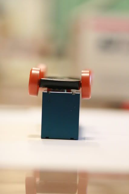
This car has a very low COM. It has a 4.1 ounce tungsten disc 0.2 ounce body and full weight wheels. If you were to cut the car off just in front of the rear wheels. You would have a weight that was very stable. It would not want to flip over by any means. In the picture you can see half of the tungsten weight is hanging below the car. It would drag on a normal track. However it runs on a Best Track and the rules allow you to go as low as you like...
I am for sure not saying this is the correct way to go. However it addresses the point of car stability and low weight. However does not address wether it is faster than other vertical COMs...
The lower the COM the more stable the car.
This car has a very low COM. It has a 4.1 ounce tungsten disc 0.2 ounce body and full weight wheels. If you were to cut the car off just in front of the rear wheels. You would have a weight that was very stable. It would not want to flip over by any means. In the picture you can see half of the tungsten weight is hanging below the car. It would drag on a normal track. However it runs on a Best Track and the rules allow you to go as low as you like...
I am for sure not saying this is the correct way to go. However it addresses the point of car stability and low weight. However does not address wether it is faster than other vertical COMs...
-
Stan Pope
- Pine Head Legend
- Posts: 6856
- Joined: Sat Jul 05, 2003 7:01 pm
- Location: Morton, Illinois
- Contact:
Re: Optimal COG distance below axle plane?
Well, I pulled a few old cars to try to observe offside wheel motion when the opposite wheel rolls over a paper match. These cars are mostly pre 1999 wheels. It appeared to me that the offside wheel tipped, keeping the axle flush against the bore! This was in slow motion, though, so the pic might be different at speed. If, indeed, the wheel tips at speed, too, then he analysis for #2 is incorrect, and lower CM will be better!Stan Pope wrote:2. A small asymmetric change in track eleveation (a small bump on one side of the rail): If the rotation is small, then there is enough play in the offside wheel bore so that the offside wheel need not move. The fulcrum, then, is located in the offside wheel bore. The rotation angle of the CM due to this bump is independent of the vertical location, but the radius is minimized when the CM is located at the axle plane. Further, the total moment of inertia is minimized when the CM mass is focused along the car's center line.
Stan
"If it's not for the boys, it's for the birds!"
"If it's not for the boys, it's for the birds!"
