
I am building the circuit on this site. I am now ready to "Test the Quad Comparator Outputs". My feeble brain needs a more detailed description of doing this.
Pic of circuit:
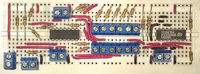
The instructions state to test for voltage across the lane's output; could someone please describe where each lane's output is on the circuit?
Thanks and Merry Christmas!


